- 您现在的位置:买卖IC网 > Sheet目录233 > LKP5660-7R (Power-One)EURO-CASSETTE 250W 2X 24V
�� �
�
�K� Series� with� PFC� Data� Sheet�
�150� –� 280� Watt� AC-DC� Converters�
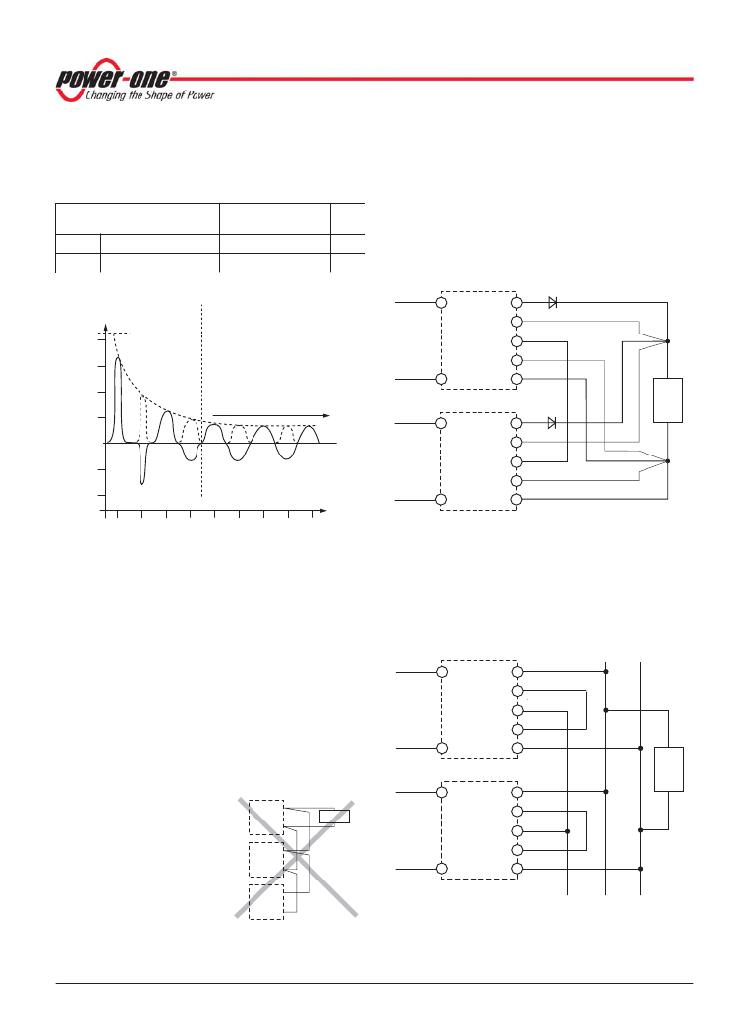
�Note:� Subsequent� switch-on� cycles� at� start-up� are� limited� to�
�max.� 10� cycles� during� the� first� 20� seconds� (cold� converter)�
�and� then� to� max.� 1� cycle� every� 8� s.�
�Table� 20:� Inrush� current� characteristics� with� option� E�
�(pin� 14:� S� –� or� Vo1–),� are� also� connected� together.� The�
�load� lines� should� have� equal� length� and� cross� section� to�
�ensure� equal� voltage� drops.�
�Not� more� than� 5� converters� should� be� connected� in� parallel.�
�The� R� pins� should� be� left� open-circuit.� If� not,� the� output�
�Characteristics�
�V� i� =� 230� VAC�
�all� models�
�typ� max�
�Unit�
�voltages� must� be� individually� adjusted� prior� to� paralleling�
�within� 1� to� 2%� or� the� R� pins� should� be� connected� together.�
�I� inr� p�
�t� inr�
�Peak� inrush� current�
�Inrush� current� duration�
�–�
�35�
�25.3�
�50�
�A�
�ms�
�Parallel� connection� of� converters� with� option� P� is� not� recom-�
�mended.�
�11036b�
�Vo+�
�1�
�2�
�I� i� [A]�
�11002b�
�S+�
�20�
�Capacitor� C� i�
�fully� charged�
�Converter�
�T�
�S–�
�1�
�15�
�Vo–�
�10�
�5�
�Normal� operation�
�(FET� fully� conducting)�
�Vo+�
�2�
�Load�
�0�
�S+�
�–5�
�Converter�
�T�
�S–�
�1�
�–10�
�t� inr�
�t�
�Vo–�
�1�
�0�
�10�
�20�
�30�
�40�
�50�
�60�
�70�
�80� ms�
�Max.� 5� converters� in� parallel� connection�
�Fig.� 34�
�Typ.� inrush� current� with� option� E�
�V� i� =� 230� VAC,� f� i� =� 50� Hz,� P� o� =� P� o� nom�
�P� Potentiometer�
�A� potentiometer� provides� an� output� voltage� adjustment�
�range� of� +10/� –60%� of� V� o� nom� .� It� is� accessible� through� a� hole�
�1� Lead� lines� should� have� equal� length� and� cross�
�section,� and� should� run� in� the� same� cable� loom.�
�2� Diodes� recommended� in� redundant� operation� only�
�Fig.� 36�
�Paralleling� of� single-output� models� using� option� T� with�
�the� sense� lines� connected� at� the� load�
�Power� bus�
�in� the� front� cover.� Option� P� is� not� available� for� battery�
�charger� models� and� is� not� recommended� for� converters�
�connected� in� parallel.�
�Option� P� excludes� the� R-function.� With� double-output�
�models,� both� outputs� are� influenced� by� the� potentiometer�
�setting� (doubling� the� voltage,� if� the� outputs� are� in� series).�
�If� the� output� voltages� are� increased� above� V� o� nom� via� R� input�
�11037b�
�Converter�
�Vo2+�
�Vo2–�
�T�
�Vo1+�
�Vo1–�
�+� –�
�control,� option� P� setting,� remote� sensing,� or� option� T,� the�
�output� current(s)� should� be� reduced� accordingly,� so� that�
�P� o� nom� is� not� exceeded.�
�Vo2+�
�Load�
�T� Current� Sharing�
�Vo+�
�Vo–�
�11003a�
�Load�
�Converter�
�Vo2–�
�T�
�This� option� ensures� that� the�
�output� currents� are� approx-�
�imately� shared� between� all�
�parallel-connected� convert-�
�ers,� hence� increasing� sys-�
�tem� reliability.� To� use� this�
�facility,� simply� interconnect�
�the� T� pins� of� all� converters�
�and� make� sure� that� the�
�reference� for� the� T� signal�
�Vo+�
�Vo–�
�Vo+�
�Vo–�
�Fig.35�
�Example� of� poor� wiring�
�for� connection� in� parallel�
�Vo1+�
�Vo1–�
�Max.� 5� converters� in� parallel� connection�
�Fig.� 37�
�Paralleling� of� double-output� models� with� the� outputs�
�connected� in� series,� and� using� option� T� with� power� bus.�
�The� signal� at� the� T� pins� is� referenced� to� Vo1–.�
�BCD20001-G� Rev� AC,� 16-Dec-2010�
�Page� 23� of� 29�
�www.power-one.com�
�发布紧急采购,3分钟左右您将得到回复。
相关PDF资料
LOK4001-2RLD
DIN RAIL 26W 5.1V
LP0125CCKW01A
SWITCH PUSHBUTTON DPDT 3A 125V
LP0125CMKW015FB
SWITCH PUSHBUTTON DPDT 3A 125V
LPI50XXX1K247XX
SWITCH PUSHBUTTON DPST 5A 12V
LRA32H2BBALN
SWITCH ROCKER DPST 10A 125V
LRA511-CR-1/012V
SWITCH ROCKER SPST 10A 30V
LRGSEK610-RS-B-A/125N
SW ROCKER DPST 20A SLD
LS1571-11-BL-BL-012
SWITCH ROCKER SPDT 15A 125V
相关代理商/技术参数
LKP5660-9ERD8
制造商:Power-One 功能描述:
LKP5660-9ERD8REP
制造商:Power-One 功能描述:
LKP5661-5R
制造商:Power-One 功能描述:AC/DC PS DUAL-OUT 24V/24V 5.8A/5.8A 280W 15PIN - Bulk
LKP5662-7R
制造商:Power-One 功能描述:AC/DC PS DUAL-OUT 24V/24V 280W 15PIN - Bulk
LKP5663-7ERG
制造商:Power-One 功能描述:
LKP5740-6R
制造商:Power-One 功能描述:AC/DC PS SGL-OUT 50.5V TO 56.5V 4.5A 254W - Bulk
LKP5740-7R
功能描述:线性和开关式电源 Euro-Cassette 231W (25.68V) Battery Charger RoHS:否 制造商:TDK-Lambda 产品:Switching Supplies 开放式框架/封闭式:Enclosed 输出功率额定值:800 W 输入电压:85 VAC to 265 VAC 输出端数量:1 输出电压(通道 1):20 V 输出电流(通道 1):40 A 商用/医用: 输出电压(通道 2): 输出电流(通道 2): 安装风格:Rack 长度: 宽度: 高度:
LKP5741-5R
制造商:Power-One 功能描述:AC/DC PS SGL-OUT 51.36V 5A 280W 15PIN - Bulk